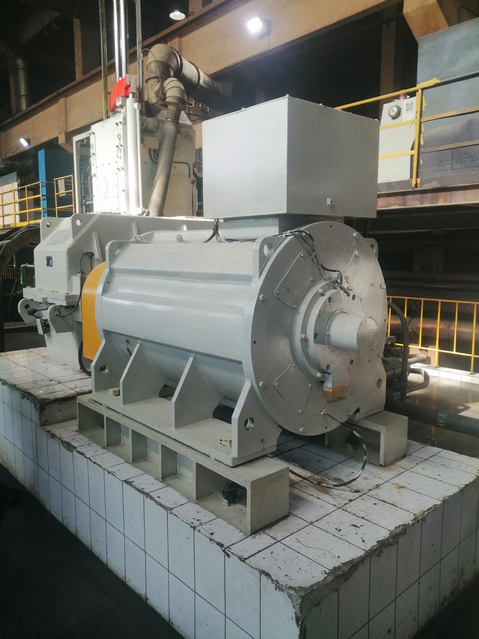
3 phase permanent magnet motor selection starts with the driven machine. A three-phase supply description tells a supplier very little about shaft torque, speed range, cooling, control, mounting, or acceptance. Those missing details determine whether a proposed motor can do useful work in the real installation. ENNENG’s archived material identifies standard, general-purpose, and customized permanent-magnet motor families, but those family records do not establish one universal rating or inverter setting. This guide shows procurement and engineering teams what to define before requesting a project data sheet.
Define the operating points before discussing frame size
List every operating point that matters, not only rated power. For each point, record shaft speed, continuous torque, peak torque, and how long the peak lasts. Add acceleration time, starts per hour, reversing, braking, dwell periods, and any need to hold torque near zero speed. A conveyor that starts loaded, a pump that follows process demand, and a mixer that sees changing viscosity can share a nominal power value while imposing very different electrical and thermal duties.
Use measured process data when it is available. If torque comes from a calculation, keep the formula, source values, and uncertainty with the inquiry. Do not convert the nameplate of an existing motor directly into a permanent-magnet motor specification without checking the driven load. The previous motor may have been oversized, operated through a gearbox, or selected for a starting condition that is absent from its nameplate.
The U.S. Department of Energy’s Motor Systems resources frame the motor, drive, and driven equipment as one system. That is the right boundary for selection. The motor should be judged by whether the complete system meets the process duty, rather than by a catalog efficiency label viewed in isolation.
Describe the electrical supply and control architecture
State the incoming supply, proposed converter, control method, and allowable cable route. A three-phase permanent-magnet synchronous motor is normally selected together with a compatible electronic drive for variable-speed industrial duty. Compatibility still has to be demonstrated for the exact motor data, drive hardware, firmware, current limits, and feedback arrangement. A drive brochure that lists permanent-magnet motor control does not prove that every motor in the same voltage class can use the same setup.
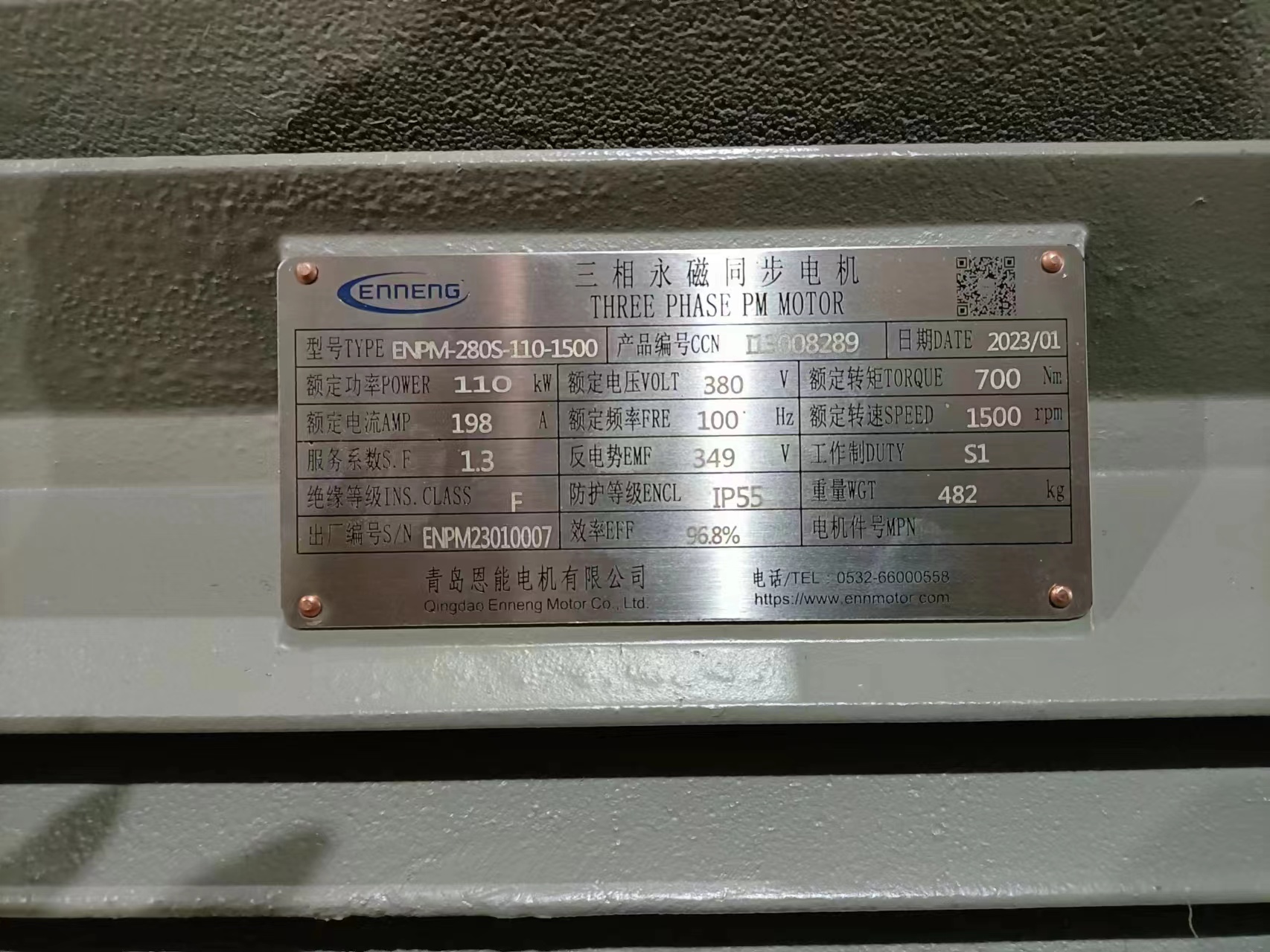
Ask the drive integrator which motor parameters are required for commissioning. Typical inputs can include rated voltage, current, frequency, speed, pole information, and electrical parameters used by the controller’s identification or tuning routine. The exact list belongs to the selected drive documentation. Unknown values should be obtained from the proposed motor data sheet, not copied from a similar frame.
Cable length, grounding, screening, output filtering, and switching conditions also belong in the design review. They can affect motor-terminal voltage stress, electromagnetic compatibility, and bearing-current risk. The DOE’s motor and drive system sourcebook provides general guidance on motor-drive systems and variable-speed applications. Project limits must still come from the actual equipment manuals and the responsible electrical engineer.
Match torque and speed as an envelope
A useful proposal shows a torque-speed envelope, not a single power number. Confirm continuous torque across the intended speed range, permissible short-duration torque, maximum mechanical speed, and any region in which available torque changes because of voltage or thermal limits. If field-weakening operation is proposed, ask the motor and drive suppliers to confirm the boundary and the allowed duty in writing.
At low speed, shaft-mounted ventilation may provide less airflow than it does near rated speed. That does not mean every low-speed application requires the same cooling solution. It means the supplier must assess losses and heat rejection at the actual duty. Specify ambient temperature, altitude, enclosure, contamination, nearby heat sources, ventilation restrictions, and available cooling utilities. Ask for the proposed cooling method and the thermal basis for continuous operation.
ENNENG’s archived TYB, TYP, and TYPCX records establish that the company presented standard, general, and customized permanent-magnet motor families. Some old tables contain inconsistent fields, so this article deliberately does not turn those records into a series-wide efficiency, frequency, or speed promise. Use the motor series overview to identify a discussion path, then require a controlled project data sheet for the offered configuration.
Fix the mechanical interface before ordering
Provide a dimensioned drawing of the driven equipment and proposed mounting. Include shaft diameter and length, key or spline details, coupling, radial and axial external loads, mounting orientation, feet or flange pattern, center height, and installation clearances. Identify which machine owns the bearings and how thermal growth or alignment will be managed. A product photograph cannot answer any of these questions.
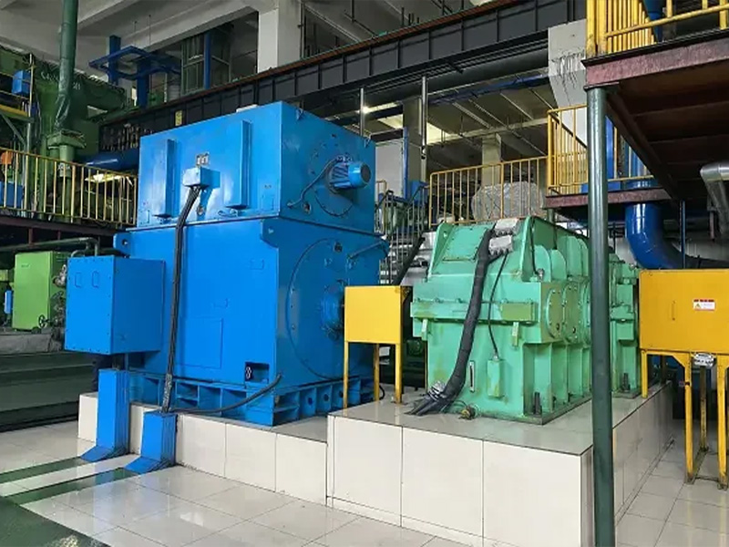
For a replacement, survey the as-built installation. Old drawings often omit field changes, shims, guards, piping, or cable obstructions. Record lifting access and the route by which the old motor leaves and the new motor enters. If the replacement changes speed or removes a transmission element, ask the driven-equipment supplier to review bearing, seal, and process limits.
Do not assign coupling or foundation responsibility by assumption. Put the motor supplier, equipment builder, installer, and plant owner on an interface matrix. The matrix should name who supplies the coupling, adapter, base, guard, sensors, cables, alignment procedure, and final drawings. That simple document prevents a technically viable motor from arriving without the parts needed to install it.
Specify protection and instrumentation
Define how winding temperature, bearing condition, overspeed, overcurrent, stall, cooling loss, and feedback faults will be detected and acted upon. The appropriate sensors depend on the motor size, duty, and risk. A sensor listed on a drawing is not useful until its signal, wiring, alarm level, trip level, and responsible controller are defined.
Ask for a protection schedule that links each monitored condition to a response. A warning may call for operator action; a trip may require a controlled stop; another fault may require immediate isolation. The motor, drive, machine, and plant control system must agree on those actions. Record the approved settings at commissioning so later maintenance does not replace them with undocumented defaults.
If the driven machine can back-drive the motor, describe that state. The electrical design may need to manage regenerated energy and safe isolation. Braking and emergency-stop behavior should be reviewed as system functions, including what happens during a supply interruption. These questions cannot be settled by the phrase “three phase” on an RFQ.
Agree on evidence and acceptance tests
Before purchase, separate three kinds of evidence: supplier declarations, design calculations, and witnessed test results. They answer different questions. A calculation may predict a thermal point that a factory cannot reproduce at full load. A routine motor test may verify construction and electrical characteristics without demonstrating the customer’s complete driven process.

Write a factory and site acceptance matrix. Identify the test condition, instrument, stabilization period, tolerance, record format, and signatory for each item. Typical checks include documentation, winding and insulation tests, sensor function, rotation, drive communication, vibration, temperature behavior, protective trips, and performance at agreed operating points. Apply only the tests appropriate to the configuration and governing project requirements.
Site commissioning should progress from static checks to controlled motion and then to loaded operation. Save the final drive parameters, drawings, nameplate record, and test results under one version. An unloaded spin can confirm direction and basic control, but it cannot prove continuous process performance. The engineering selection guide gives a broader structure for motor, mechanical, and site inputs.
Send a decision-ready RFQ
A useful RFQ contains the driven-machine description; torque-speed duty; supply and drive information; ambient and cooling conditions; mechanical drawings; control and feedback needs; protection philosophy; required standards; documentation language; test plan; delivery boundary; and installation constraints. Mark estimated values as estimates. Ask the supplier to list assumptions, exclusions, and missing data in its return proposal.
Compare offers on the same boundary. One quotation may include a converter, encoder, cooling package, tests, and documentation while another lists only the motor. Create a compliance table against the RFQ rather than comparing headline power and price. Differences that appear commercial may actually be differences in scope or accepted duty.
ENNENG’s archived company sources support the existence of its permanent-magnet motor R&D and manufacturing activity and several motor-family categories. They do not prove that an unreviewed model meets a new application. Send the measured operating envelope for a configuration discussion, and keep the selection open until a project-specific data sheet, interface drawing, and test basis have been approved.
Evidence boundary
This article uses ENNENG knowledge records CAND-002 for the company’s permanent-magnet motor activity and CAND-003, CAND-004, and CAND-005 for the existence and limitations of the archived TYB, TYP, and TYPCX families. Those records remain company-source candidates and must be checked against controlled material before an indexed release. External engineering context comes from the U.S. Department of Energy Motor Systems page and Improving Motor and Drive System Performance. Neither source certifies an ENNENG product or a particular project selection.