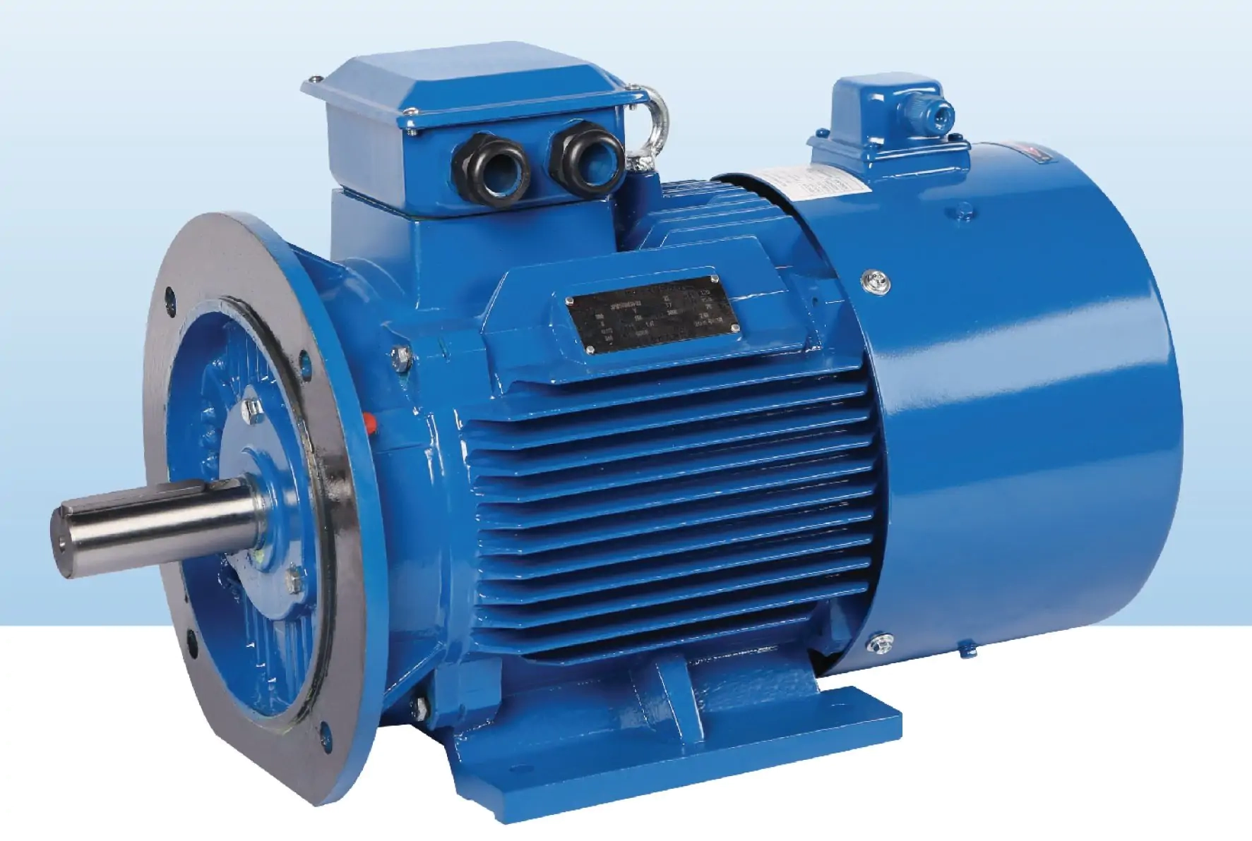
Permanent magnet motor applications fill the first slide, but the motor picture is missing. In its place are a pump, extruder, compressor, conveyor, mixer, and one direct-drive machine. All six might use a PMSM. They won't share one frame, cooler, feedback choice, or inverter. The meeting has to decide where the technology fits and what evidence each application still needs.
What follows is an illustrative review, not a customer result. No machine on these cards has been approved. The cards simply make the selection questions visible.
The review starts with the process shaft
Six cards sit on the table. Their power figures overlap; their sketches don't. Pump: a mostly stable curve. Conveyor: material already on the belt at start. Mixer: viscosity changes through the batch. Extruder: broad speed range with persistent torque. Compressor: speed and process control tied together. Direct drive: high torque close to zero speed.
The team writes speed and torque together. Continuous points go in black. Peaks go in red with their duration and repetition. Starts, reversals, braking, inertia, dwell, and any loaded operation near zero speed are added. Where the load was calculated, the formula stays attached. Where nobody knows, the card says unknown.
That last word, unknown, creates a measurement task. It does not silently become a bigger motor. A larger motor could pull the drive, cable, cooler, base, and lifting plan upward with it. On the PMSM torque-speed curve guide, the team pins known points and leaves the uncertain corner open.
Pumps and fans need the whole operating curve
The pump card has a dot at rated duty. The reviewer draws the rest of the curve around it. Where will minimum flow sit? Where is maximum demand? How will flow be controlled, and how often will the process visit each region? A bypass or throttle is marked too. The far corner may matter, but the machine might rarely stay there.
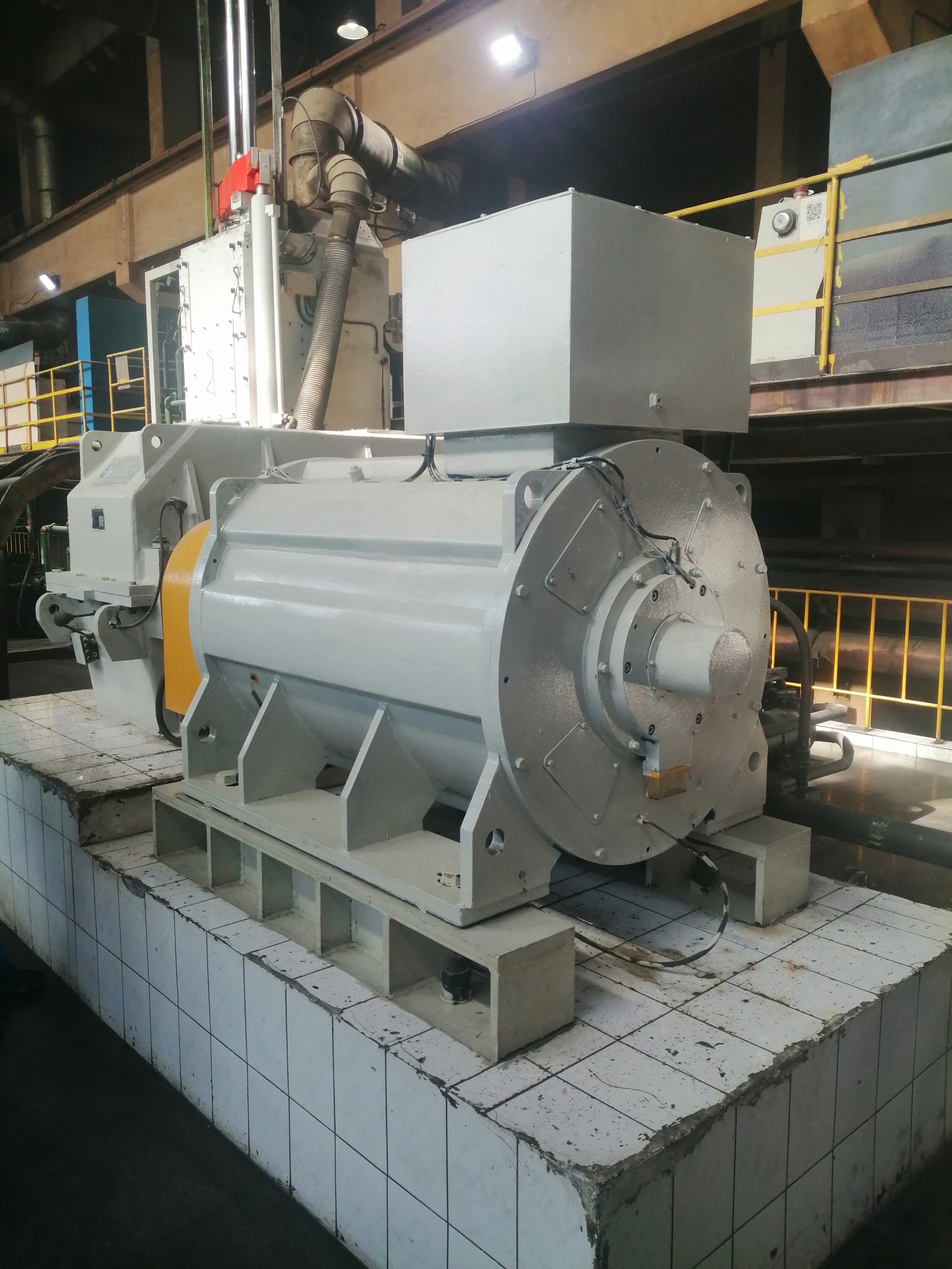
The team also checks starting and stopping. Can flow drive the shaft backward? Will the process regenerate during deceleration? Does the application require a flying start after a brief supply interruption? These questions affect the inverter and protection even when the continuous torque looks uncomplicated.
The shaft fan slows with the shaft. Torque may not. That mismatch puts a question mark beside cooling at low speed. A separate blower would need power and proof; a liquid loop would need water, piping, drainage, and access. The words “variable speed” answer none of those site questions.
Conveyors make starting torque visible
Two starts are drawn on the conveyor card. Empty is easy. Fully loaded brings belt tension, incline, breakaway, acceleration time, start frequency, and rollback into the room. The brake and backstop are not erased just because another drivetrain part might be.
“Do we only care about speed?” the controls engineer asks. Probably not. A torque limit may protect belt and process, while a loaded start may push the design toward feedback. If that means an encoder or resolver, the quote also needs its card, cable, connector, mounting, and a way to replace it.
The PMSM vector-control guide helps turn those questions into commissioning inputs. It also keeps a drive brochure from being mistaken for proof that one parameter set fits every motor winding and duty.
Mixers and extruders are thermal stories
The mixer does not hold one torque for one hour. It moves through a recipe. One stage is light; another becomes thick; a cleaning cycle may run at a different speed. The review therefore uses a torque-speed-time sequence rather than an average number. Peak duration and cooling recovery between stages stay visible.
The extruder trace looks calmer until product and temperature change. Then torque moves. Screw design and speed range move it again. A slow point may trouble the thermal design more than the nameplate point. On a second sheet, the team draws shaft load, coupling, torsional path, alignment, and the gearbox that still remains.
For both applications, the acceptance plan needs agreed material or a defensible simulated load. An unloaded factory spin can check direction and basic control. It cannot prove the thermal behavior of the production cycle. When full process load cannot be reproduced, the factory and site portions of the evidence should be divided before the order.
Compressors join motor, drive, and process control
The compressor card cannot stay in the electrical pile. Its map comes to the meeting. The group marks running speed, pressure control, acceleration, minimum stable operation, process limits, stopping behavior, and auxiliaries. A motor chosen away from that map would be unfinished work.

Ownership is read aloud. Who sets torque and speed limits? Who writes interlocks and restart logic? Where do local controls, communications, and emergency stop land? The electrical notes add cable length, grounding, filters, harmonics, and braking. The site sketch adds heat, altitude, dust, ventilation, and access.
In the U.S. Department of Energy Premium Efficiency Motor Selection and Application Guide, PM synchronous motors appear inside the wider industrial selection problem. The team draws that same boundary around the drive, motor, transmission, and load. Moving a problem across one line does not remove it.
Direct-drive work changes the mechanical question
The direct-drive card has no reduction stage to hide behind. One concept couples at process speed. Another bolts onto the machine; a third shares its shaft arrangement. To make high torque slowly, diameter and pole count may move, followed by active material, bearings, frame, and heat path. The installed shape now competes with the power number for attention.
At the machine, a tape measure replaces the archive drawing. Shaft and centerline come first, then runout, bolts, base, and free space. Load arrows show radial force and thrust; a note names the bearing owner. If the gearbox also carried structure, red ink marks possible new steel. The 3 phase permanent magnet motor selection guide covers the wider input set.
ABB's recent permanent magnet motor series announcement identifies variable-speed applications in geared and direct-drive arrangements for its cited range. That supports the breadth of the technology, but it does not transfer ABB performance claims to ENNENG or approve any application described here.
Environment can rule an application in or out
One card says “indoor industrial.” Gone. The bay is hot, dusty, and awkward to clean. Another motor sits outdoors; a third has poor access to cooling water. Numbers replace the vague label: temperature and altitude first, then humidity, contamination, orientation, ingress, utilities, and any hazardous-area rule.
The environment reaches into the design. Bearings and seals feel it. So do coatings, heaters, drains, terminals, sensors, and enclosure. The maintenance lead adds one more test: can the motor be inspected and removed without dismantling half the process?
“IEC design” gets a question mark. Which part? Which edition? Rating, testing, enclosure, cooling, mounting, vibration, noise, insulation, and efficiency are not one requirement. The project has to name what applies.
The application decision uses evidence, not a technology slogan
Four boxes finish the sheet. Process fit asks whether every duty point lies inside the envelope. Integration fit asks whether drive, feedback, cooler, mechanics, controls, and protection work together. Evidence fit holds calculations, drawings, and tests. Commercial fit holds scope, dates, support, and the assumptions behind lifecycle cost.
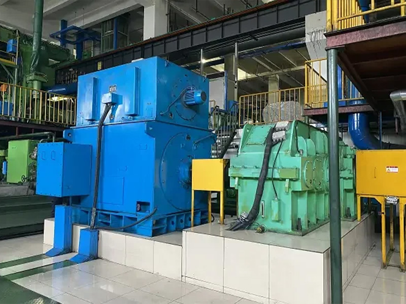
A PMSM may finish first. It does not start there automatically. Every architecture is compared at equal process output, with energy, maintenance, footprint, complexity, site work, spares, and startup inside the same boundary. A saving without its baseline stays off the scorecard.
The company evidence has a narrow role. ENNENG-CAND-002 records archived PM motor activity. ENNENG-CAND-003, 004, and 005 record three historical family categories; ENNENG-CAND-010 records a customization statement. None proves suitability, efficiency, certification, or savings for a new duty. Review the motor series context, then send the measured duty.
Evidence boundary
DOE and ABB provide general application and system context. ABB speaks for the products on its own page. The admitted ENNENG records support only the company statements identified above. Approval still rests on the offered data sheet and torque-speed envelope, then the interface, cooling and protection documents, and finally the agreed tests.