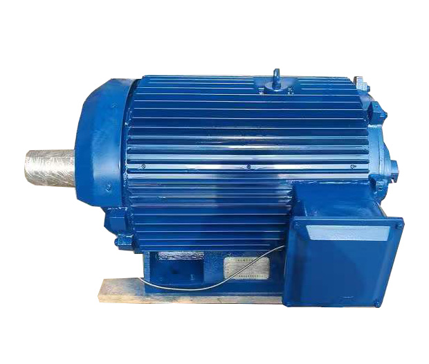
Permanent magnet motor factory acceptance test is written across the cover of a red folder. Inside it, an illustrative project team finds three versions of the outline drawing, a torque curve with no revision, and an invitation to “witness the motor test.” They stop there. Which motor? Which settings? What test?
That pause is useful. A witness can come home with evidence. It can also come home with a few photographs and no answer to the purchase question. That distinction is made before travel.
The red folder: what exactly is being tested?
The buyer opens a blank identity sheet. Order number goes first. Then the production or serial identifier, drawing revision, winding data, rotor arrangement, cooler, feedback device, sensors, terminals, and the converter planned for the test floor. One line is left for late changes. If that line fills, the test program gets another look.
Next comes the duty map. Black marks the places where the motor must stay. Red marks the brief excursions, and every red mark gets a time beside it. Around the edge are maximum speed, direction, starts, braking, coolant, ambient basis, and the field-weakening corner if one is expected. The PMSM torque-speed curve guide helps the team keep a peak from quietly turning into a continuous promise.
One box is titled “not reproduced here.” It might hold process inertia, a long site cable, plant ventilation, or the final control sequence. Nobody hides that box. Each item moves to a calculation, another subsystem test, or the site plan.
Drawings first. Power later.
Before the motor runs, the team places the approved interface drawing beside the unit. Shaft and flange agree? Mounting position? Terminal box direction? Someone tries the lifting sketch against the real frame. Another person finds the cooler ports and sensor exits. Mass, bearings, and wrench space are no longer notes in separate files; they are things the group can point to.
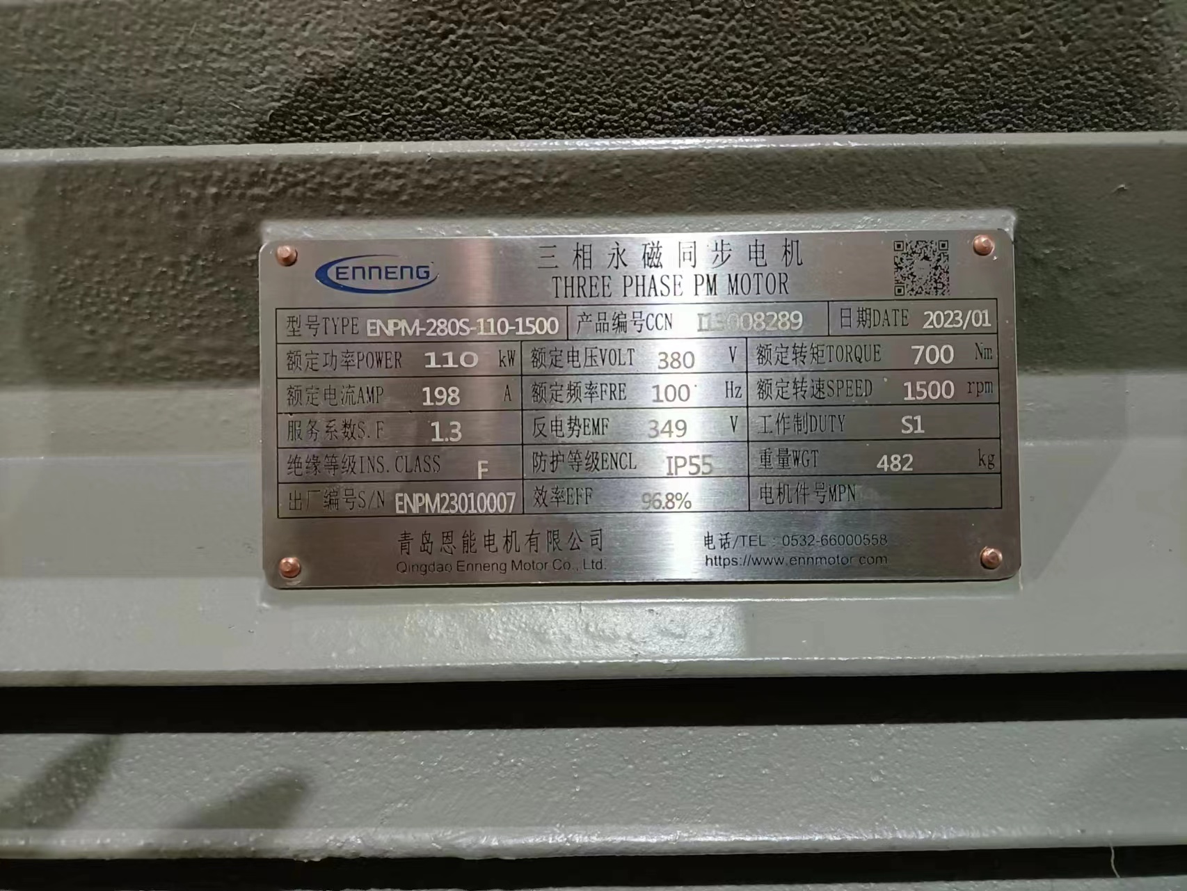
The record list is shorter than a generic quality manual. It names only what this order needs. Winding and insulation records may be on it. So may magnet or rotor controls, balance work, instrument calibration, inspection hold points, and the disposition of a nonconformance. A file called “quality documents” earns a question mark. A named record, revision, and unit reference can earn acceptance.
Company history has a limited role here. The archive adds background, with firm limits. ENNENG-CAND-002 records a company statement about PM motor R&D and manufacturing; CAND-003, 004, and 005 record three past family categories. None of those old pages can sign today's test sheet or prove the offered unit's rating. The current folder has to supply that evidence.
The tape measure gets its turn
Nameplate first, shipping supports last. Between them, the witness works slowly around the frame: a loose entry here, an unprotected shaft there, then ground points, paint, rotation marks, sensor tails, drains, cooler ports, and any fitted heaters. It is ordinary work. That is why it catches ordinary mistakes.
Then the tape comes out. Paint can wait. Will the shaft enter the coupling? Will the pilot locate? The measurement sheet moves from extension and key or spline to flange, bolt circle, center height, feet, encoder clearance, and cooler fittings. Each critical dimension gets an instrument and a recorded result. Photographs sit beside the numbers; they don't replace them.
Packing is part of this walk. How will the shaft be protected? Are openings sealed? What happens during humid storage? Where can a crane lift? A motor that passes electrically can still arrive unusable after a careless journey.
Electrical checks earn permission to continue
Resistance and phase identity come back first. Insulation and earth continuity follow, then the temperature devices, heaters, and accessories. Good results allow the program to continue; the torque curve still waits for a different test.
The procedure matters here. Which test value? Which temperature correction? Which limit? Before applying an insulation test, the technician traces where it could travel. Sensors, surge parts, electronics, and the converter are disconnected or protected according to the agreed sketch. Nobody should invent that boundary beside the machine.
For the standards row, the team opens IEC 60034-1:2026. Its rating and performance framework covers rotating machines within the publication's scope. It also treats the motor component separately from the wider power drive system when active converter parts are integrated. That is more precise than writing “IEC motor” on a purchase order. The order should name the applicable requirements and any additions from the industry or site.
The no-load run has a narrow job
The shaft turns. Direction is right. Speed feedback follows. Drive communication works. A faint noise or leak is easier to find now than after packing. Accessories are exercised. Current, voltage, temperatures, and vibration are written down.
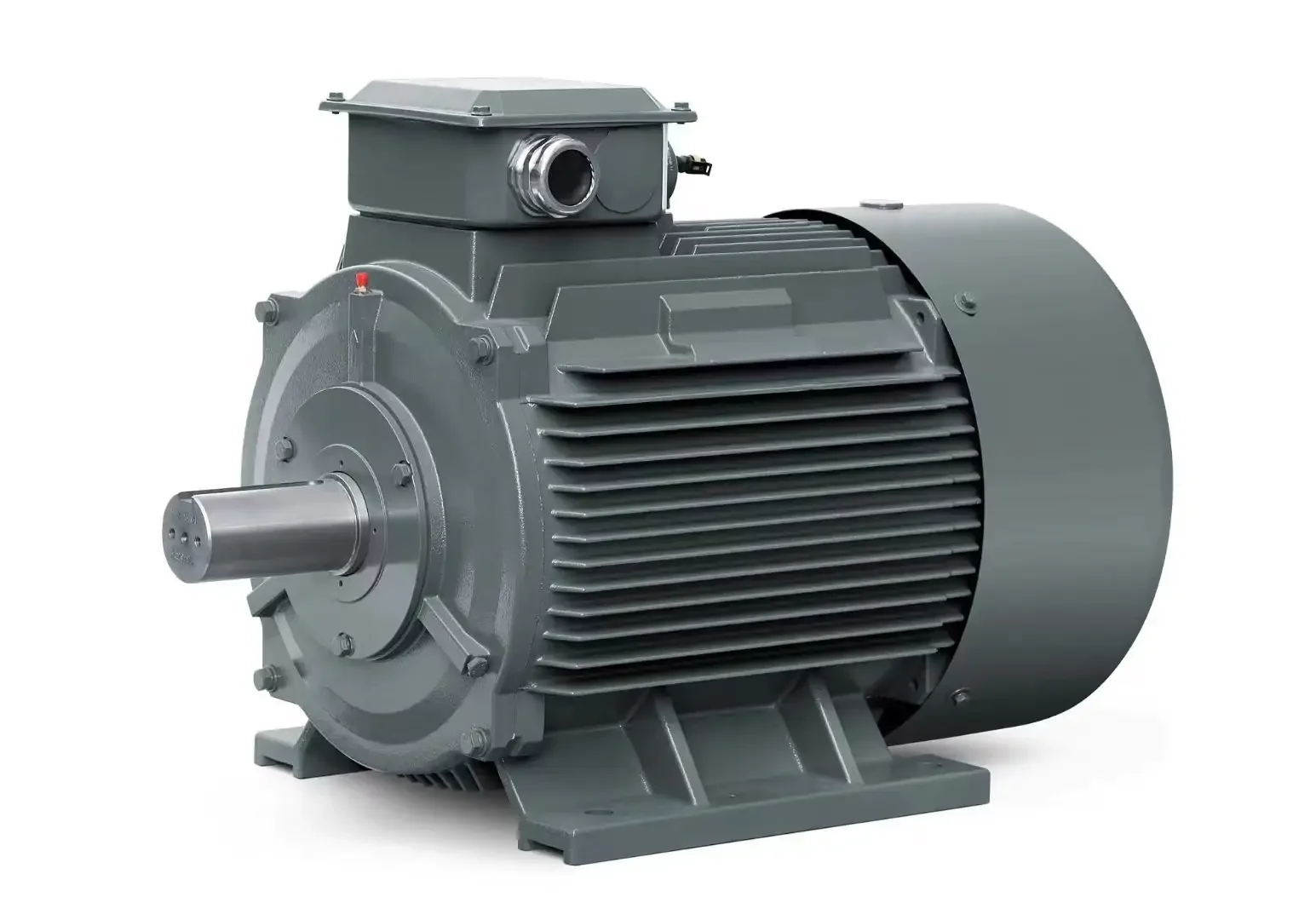
The margin beside those numbers describes their surroundings: support, mount, coupling state, speed, converter, switching, coolant, stabilization, sensor point, and instrument bandwidth. Remove the margin and the vibration value becomes a poor traveler.
When the agreed vibration method refers to IEC 60034-14:2018, the witness reads the scope too. The publication addresses factory acceptance procedures and limits for certain uncoupled machines, under stated conditions. The witness checks that scope before copying a limit. A test on a factory support cannot promise what a flexible base and process machine will do later. If the purchased unit or coupled test sits outside the standard condition, the parties write another agreed method.
The load map is where promises meet instruments
On the test sheet, every required point has speed, shaft torque or power, time, coolant condition, and the temperatures to watch. The team draws a heavy line around the measurement boundary. Is this motor-only? Does it include the converter? Cooler pumps? A separate blower? An unexplained efficiency percentage is not allowed to cross that line.
IEC 60034-2-1:2024 sets out methods for finding efficiency and losses for machines within its scope, including synchronous machines. A standard offers methods; it does not choose one for this order. A large configuration may make full-load work unrealistic. In that case the parties can agree on another recognized route, calculations, or selected load points, and the report names the route without dressing it up.
Converter details remain attached: cable, filter, switching frequency, control mode, feedback, current limits, and software or parameter revision. Results from the factory drive describe that arrangement. They do not give every site converter a free pass.
Feedback should survive more than a green light
The encoder status light is green. The shaft turns the wrong way on the screen. That small example is why the check follows the signal from supply and polarity through mounting, cable, shield, card, scaling, direction, and speed range. Sensorless control gets its own question: over which operating region is the supplier accepting it?
Faults are read as short stories. A winding sensor rises. Who sees it? At which value? After what delay? Does the drive warn, reduce load, coast, stop, or trip? What permits a restart? The conversation is repeated for a hot bearing, lost cooling, too much speed or current, missing feedback, broken communications, and emergency stop. Only conditions that the setup can handle safely are demonstrated.
The PMSM vector-control guide carries that review into commissioning. At the factory gate, the useful handover is a controlled drive file and protection schedule. No drive type, firmware, or revision? Then the screenshot is a souvenir, not a controlled file.
The thermal clock runs on the machine's time
The thermal test clock starts after the duty and cooling are stable, not when the witness becomes impatient. Ambient or inlet coolant, flow, mounting, test point, sensor method, reference temperature, and acceptance limit stay visible. So does the chosen stabilization rule.

Low speed gets a separate look. Torque can remain substantial while a shaft fan slows. A brief rated-speed run may never reveal that corner. Where the facility cannot hold the real low-speed duty, calculations and component evidence can cover part of the question; the installed cooling and protection then become named site tests.
The temperatures settle within the agreed limits. Good. That one run still says nothing about an unlimited life; bearings, insulation, magnets, the cooler, and contamination keep their own limits. The result says what happened under the recorded condition. Nothing broader.
The closing meeting has paperwork to finish
The closing page is untidy on purpose. Completed tests sit beside deviations, retests, open actions, and names. The clean summary does not replace the raw readings. Instrument IDs and calibration status remain. So do calculations, tolerances, photographs where useful, witness names, and signed dispositions.
A concession sits beside the report that needed it. Otherwise the two will be separated by the first hurried handover. Into the release package go the final data sheet and drawings. The manual, drive file, sensor list, spares, packing record, and site plan follow behind them.
What was accepted? This unit, under these conditions, against the agreed evidence list. Nothing larger is implied. It is not approval for every future speed, load, drive, cooler, or mounting.
The site still has work to do
Factory walls cannot reproduce a foundation simply by describing it. Final alignment, structure, long cable, cooling utilities, plant interlocks, process load, and emergency-stop integration remain installation questions unless the test truly included them.
The site sequence starts gently: inspection, wiring and insulation checks, controlled rotation, coupled low speed where appropriate, protection, then agreed loading. Temperature and vibration points keep the same names used in the factory record. That gives maintenance a real baseline.
ENNENG-CAND-010 supports a historical statement about tailoring a replacement motor to user requirements. Some requests will work; others will not. The offered design decides. Buyers can review the permanent magnet motor product routes and send the duty, interface, and witness points for a current configuration discussion.
Evidence boundary
IEC sources provide general rating, efficiency, and vibration frameworks within their scopes. They don't certify an ENNENG product. The admitted ENNENG records support only the history and family statements identified here. Final acceptance belongs to the current order, approved data sheet, selected standards, signed test plan, actual results, and closed deviations.