
PMSM vector control commissioning succeeds when the motor data, feedback strategy, current limits, and process duty are agreed before the first run. Selecting “permanent magnet motor” in a drive menu is only the start. The controller must know enough about the actual machine to separate torque-producing and flux-related current, estimate or measure rotor position, and stay within electrical, thermal, and mechanical limits. This guide turns those requirements into a practical engineering checklist.
Start with the exact control objective
Define what the driven machine must do in measurable terms. State the minimum and maximum speed, continuous and peak torque, speed accuracy, allowable response time, acceleration and deceleration, starts per hour, reversing duty, and behavior near zero speed. Add position-holding or indexing requirements if they exist. A fan with a smooth speed reference does not demand the same control behavior as a loaded extruder, hoist, or cyclic machine.
Decide which party owns the process loop and which owns the motor-current loop. The plant controller may command speed or torque while the inverter closes faster internal loops. Define reference scaling, ramp limits, interlocks, safe states, and what happens when communication is lost. The U.S. Department of Energy's Motor Systems program treats the motor, drive, and driven equipment as one system. That boundary prevents a controller from being tuned in isolation from the load it must move.
Choose feedback from the low-speed requirement
Vector control needs rotor-position information, obtained either from a physical sensor or from an estimator. Sensorless operation can reduce hardware, but its usable speed and torque range depend on the controller, motor saliency, parameter quality, and duty. If the application needs repeatable torque at standstill, accurate positioning, controlled loaded starting, or rapid reversal, ask the drive supplier to confirm in writing whether its sensorless method meets that exact condition.
For sensored control, specify encoder or resolver type, resolution, supply, signal format, connector, cable, shielding, and mechanical mounting. Confirm direction and electrical angle during commissioning. Feedback faults require a defined response: coast, controlled stop, mechanical brake, or process shutdown. Avoid treating the sensor as an accessory selected after the motor. Its interface card, installation, and diagnostic coverage are part of the control architecture and the acceptance test.
Gather the motor parameters the drive actually uses
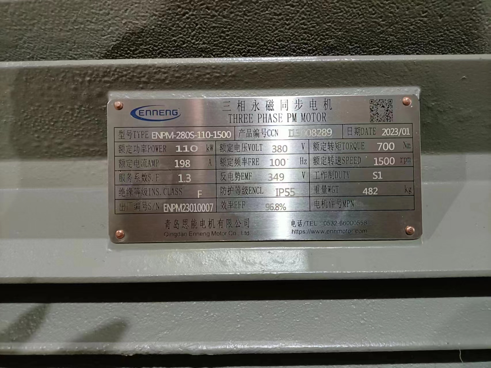
Provide the controlled project data sheet rather than a photo of a similar nameplate. Typical required data can include rated voltage, current, frequency, speed, power, pole pairs, winding connection, resistance, inductance information, flux or back-EMF data, inertia, and permissible current or speed limits. The exact set is drive-specific. Use the drive manual's parameter list and ask the motor supplier to identify values that require a test or calculation.
Do not copy parameters from another frame or let an auto-tune routine hide missing engineering decisions. Some identification procedures are stationary; others rotate the shaft. Some require uncoupling the load. Record which procedure is permitted, its preconditions, and the expected movement. ABB's official Technical Guide No. 1 on direct torque control explains the general development of field-oriented and direct-torque approaches. It is useful background, while the selected inverter manual remains the governing commissioning document.
Set current, voltage, speed, and thermal limits together
Torque command ultimately becomes current, so the continuous and peak current settings must correspond to the approved motor envelope. Define peak magnitude, duration, and repetition. Confirm the drive's derated output current at the site ambient, enclosure, carrier frequency, and altitude. A current setting that permits a brief acceleration may overheat the motor if a stalled process holds it too long.
Voltage limits shape the high-speed region. Above the normal base-speed range, the controller may use field weakening, which reduces available torque and introduces additional overspeed and back-EMF concerns. Set motor maximum speed, process maximum speed, and drive velocity limits explicitly. Wire winding-temperature sensors where supplied and define alarm and trip actions. The torque-speed curve guide explains how these current, voltage, and thermal boundaries should appear on one operating map.
Engineer the cable and grounding path
Motor cable length and construction influence terminal voltage stress, electromagnetic emissions, common-mode current, and feedback noise. State the route, approximate length, conductor size, shield arrangement, grounding method, and whether output reactors or filters are proposed. Follow the inverter and motor manufacturers' limits; do not assume practices from an induction-motor installation transfer unchanged to a PMSM project.
Keep power and feedback wiring separated according to the equipment instructions. Bond screens and protective earth as designed, not according to whichever termination is easiest in the field. If bearing-current mitigation is required, assign responsibility for insulated bearings, grounding devices, filters, or common-mode measures. Include the final cable and grounding drawing in the as-built package because future cable replacement can change the electrical environment seen by the motor and controller.
Plan tuning around the coupled machine
Mechanical inertia, backlash, compliance, resonance, and process disturbances influence speed-loop tuning. Begin with conservative gains and the manufacturer's procedure. Verify direction, feedback polarity, and torque sign at low risk before increasing bandwidth. If the drivetrain has a flexible coupling, long shaft, or large roll, involve the machine builder; an aggressive loop can excite a resonance even when the motor and inverter are electrically compatible.
Capture trends during steps and ramps: reference, actual speed, torque-producing current, bus voltage, feedback status, and relevant temperatures. Look for overshoot, oscillation, current saturation, or repeated limit intervention. Tune to the process need rather than the fastest response available in the menu. Document the final values and why they were chosen. A parameter backup without an acceptance record says what was loaded, but not whether the coupled system met its requirement.
Define faults and safe states before production
List loss of feedback, overspeed, overcurrent, overtemperature, cooling failure, communication loss, DC-bus overvoltage, ground fault, emergency stop, and external back-driving. For each event, state who detects it, how quickly the system must respond, what stop category or mechanical action follows, and how restart is authorized. Permanent magnets can generate voltage whenever the rotor turns, so isolation and maintenance procedures must consider motion from the driven machine.
Test critical protective functions under controlled conditions. Do not disable a trip merely to finish commissioning. If a nuisance trip occurs, identify whether the cause is an incorrect threshold, a wiring or feedback fault, unstable tuning, an unrealistic ramp, or a genuine process overload. Preserve the fault log and corrective action. The VFD compatibility checklist covers additional motor-drive pairing questions for procurement and design review.
Use a staged commissioning and acceptance plan
The first stage is document verification: motor and drive identities, firmware, wiring, grounding, cooling, feedback, and entered parameters. The second is static and low-speed testing with the machine in a defined safe condition. The third adds acceleration, deceleration, direction changes, and representative process load. The final stage holds agreed operating points long enough to assess thermal behavior and repeats transient events at their actual frequency.
Acceptance criteria should specify speed error, response, maximum current, allowed temperature, vibration, protective actions, and process output. Name the instruments and sampling method. Save trends and parameter files with a version and date. If the motor, drive hardware, firmware, feedback device, or cable changes later, review which tests must be repeated. This turns commissioning from a one-time adjustment into a traceable engineering baseline.
Prepare a vector-control RFQ package
Send the driven-machine description, torque-speed-time profile, supply, proposed drive, cable route, cooling and ambient conditions, feedback need, mechanical inertia, stop behavior, protection philosophy, and required acceptance tests. Ask the drive vendor to name the exact control mode, firmware and option hardware. Ask the motor supplier for the parameters and operating envelope required by that mode. Record assumptions and open items in a compliance table.
ENNENG's archived material supports knowledge references ENNENG-CAND-002 for permanent-magnet motor activity, ENNENG-CAND-003 and ENNENG-CAND-004 for standard and general motor-family context, and ENNENG-CAND-010 for a stated customization service. These records do not prove compatibility with every inverter or an unlimited custom range. Review the PMSM product context and send the complete control duty for a project-specific response.
Evidence boundary
This article uses official DOE system-level guidance and ABB control background for general engineering context. The ABB document does not prescribe settings for an ENNENG motor, and the company-source candidate records do not certify a particular motor-drive pair. The final authority is the approved motor data sheet, drive manual, wiring drawings, risk assessment, and witnessed acceptance record for the exact equipment revision.